SMART AMBIENT LIGHTING
Status: Hardware Prototyping — In Progress
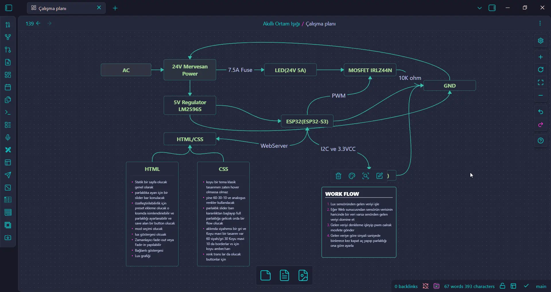
An autonomous IoT lighting system. Designed to track real-time environmental lux levels (like sunsets) and adjust 24V/5A power electronics seamlessly using a dual-core FreeRTOS architecture. Protected by a MQTT network design.
TECHNOLOGIES & PLATFORMS
SYSTEM ARCHITECTURE
[1] SENSING (BH1750)
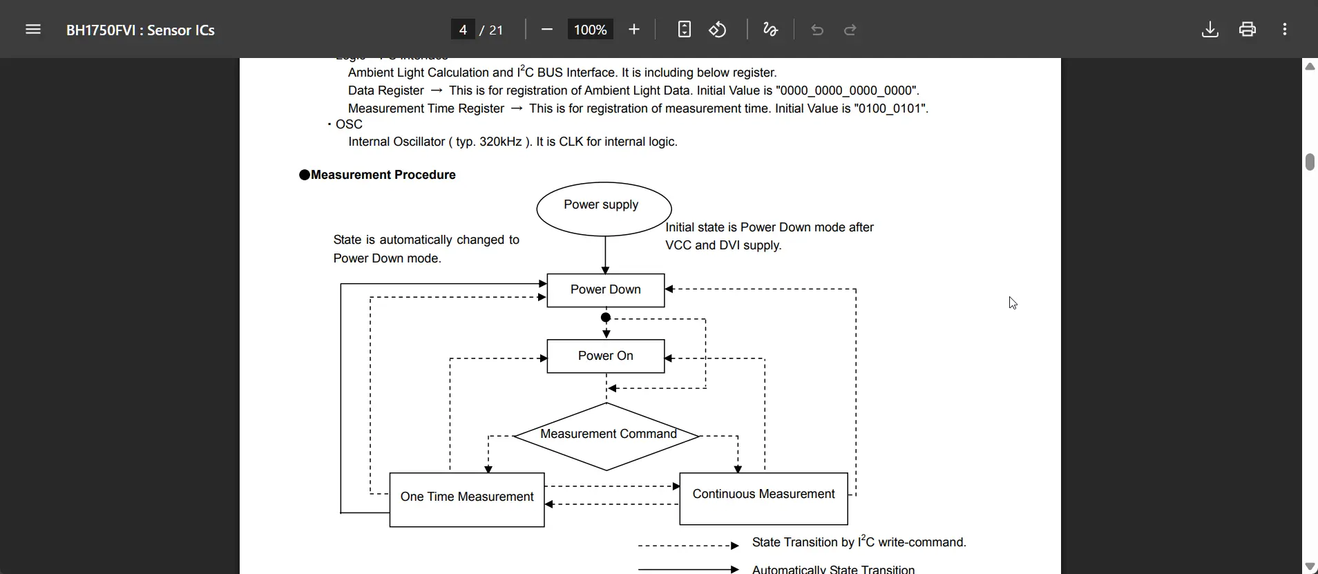
  → I2C digital read for exact Lux levels
  → Replaces noisy analog LDRs
         ↓
[2] LOGIC & PROCESSING (ESP32 FreeRTOS)
  → Core 0: Wi-Fi polling and MQTT network subscriptions
  → Core 1: Hardware PWM generation (LEDC) & PID Controller
         ↓
[3] POWER ELECTRONICS (IRLZ44N)
  → 3.3V logic signal rapidly switches the massive 24V/5A load
  → PWM prevents the N-Channel MOSFET from overheating
         ↓
[4] MANUAL OVERRIDE
  → Master Dashboard requests confirmation before dispatch
  → Fallback to Local AP Mode if the main router drops
ENGINEERING FOCUS
MOSFET Power Switching
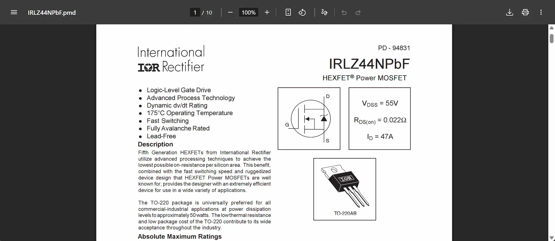
Since the microcontroller cannot drive heavy loads directly, an IRLZ44N logic-level MOSFET acts as a rapid switch, safely isolating the 3.3V logic circuit from the 24V power circuit.
Thermal Management via PWM
By switching the circuit on and off rapidly (PWM) instead of lowering voltage linearly, the system minimizes power dissipation and prevents the MOSFET from burning up under load.
Dual-Core FreeRTOS
The ESP32 runs Wi-Fi/MQTT blocking functions on Core 0 and the mission-critical hardware PWM fading on Core 1, ensuring the lights never freeze or stutter during network reconnects.
HARDWARE BOM RATIONALE
| Component | Selection | Engineering Justification |
|---|---|---|
| Microcontroller | ESP32 | Dual-Core architecture allows splitting network tasks from hardware PWM tasks, crucial for stability. |
| Switching MOSFET | IRLZ44N (N-Channel) | Logic-level threshold (turns on at lower voltages). Can comfortably handle the 5 Amps of current without extreme resistance. |
| Light Sensor | BH1750 (I2C) | Provides highly precise 16-bit digital Lux values directly over the I2C bus, immune to the voltage drop noise of analog sensors. |
| Voltage Regulator | LM2596 Step-Down | Drops the main 24V power supply down to a clean 5V to safely power the ESP32 logic board. |
EXECUTION ROADMAP
The project follows a strict "Virtual to Physical" engineering pipeline to eliminate hardware risks before soldering.
Phase 1 — Code & Simulation (Wokwi)
Proving the logic purely in the browser. Testing FreeRTOS core delegation, LEDC hardware PWM fading, I2C BH1750 sensor reading, and Wi-Fi/Web Server routing before touching physical hardware.
Phase 2 — Breadboard & Smoke Test
Wiring the IRLZ44N and ESP32 with a small test load. Validating heat dissipation, PWM frequency hum, and MQTT latency over the local network.
Phase 3 — KiCad PCB Design
Designing the industrial schematic. Tracing ultra-thick paths for the high-current power lines and routing the logic layer. Producing the GERBER files for manufacturing.
Phase 4 — Fusion360 Enclosure
Designing a 3D-printable housing based on the exact PCB dimensions, incorporating ventilation grilles for thermal exhaust and a dedicated mount for the BH1750 sensor.